Activity
Mon
Wed
Fri
Sun
Nov
Dec
Jan
Feb
Mar
Apr
May
Jun
Jul
Aug
Sep
Oct
What is this?
Less
More
RMS Auto-electrics/Diagnostics
103
5.0
$34/m
4 contributions to RMS Auto-electrics/Diagnostics

11h •
2014 Ford Fiesta 1.5 TDCI UGJC
Hi was wondering if anyone else on here has experienced the same issue I’m having? Currently have a Fiesta in with warnings on in limp mode and storing fault code “P2121-00 Throttle / Pedal Position sensor / switch D circuit range/performance. What’s been done so far: - check live data and confirm pedal position sensor D is reading and percentage changes when pedal is operated although there is a delay (may be diagnostic tool causing delay) but position sensor E will not read at all stays at 0% although if engine is run for a short time it will give intermittent reading not always in line with sensor D and never steady. - Pedal line checks done following diagram on Alldata and confirm voltage supply and grounds present. - Carry out line checks between pedal and instrument cluster and power train units all below 0.6ohms - Pedal replaced with know good unit (used) love data results exactly the same - Instrument cluster sent off to ECU testing to be checked no faults with cluster identified refitted At this point I’m lost with how to continue fault finding the wiring diagram shows 2 position sensors within the pedal but I’m only getting one readout am I looking for something that doesn’t exist or should I have two constant readings? If so how do I tell which is sensor D and which is E on the diagram as it seems one reports to the PCM and one reports to the instrument panel? Thanks in advance for any help or tips 👍
0 likes • 10h
That’s the wiring diagram I have been using
0 likes • 5h
latest update of what I’ve found so far Signal line between APP and ICM within range quick response when checking on scope operating between 0.4V (pedal released) and 3.2V (fully depressed) Signal line between APP and PCM on the other hand is not responding while operating pedal I’m using the two channel scope built into my snap on diagnostic tool and I am still learning when it comes to scoping, I thought I had recorded results to attach here but unfortunately I can’t find them there was however known good wave patterns for both signals in the guided test function and as mentioned above and when following that guided test signal to Instrument Cluster was as expected but the PWM signal to the PCM stayed flat All results for above voltages have been recorded from back probing the connector with ignition on I have two throttle pedals the original and a known good pedal and when swapped out the results stay the same
🍀
Aug 10 •
Load cages 5amp,2amp 0.5amp
Our load cages are all ready to dispatch,I’m away in two weeks but when I’m back I will be contacting you for your addresses and will be sending them out in small batches.

0 likes • 11h
Is there a link to order @Robert Shervill ?

0 likes • Apr 17
Congratulations 😃
🍀
Mar 18 •
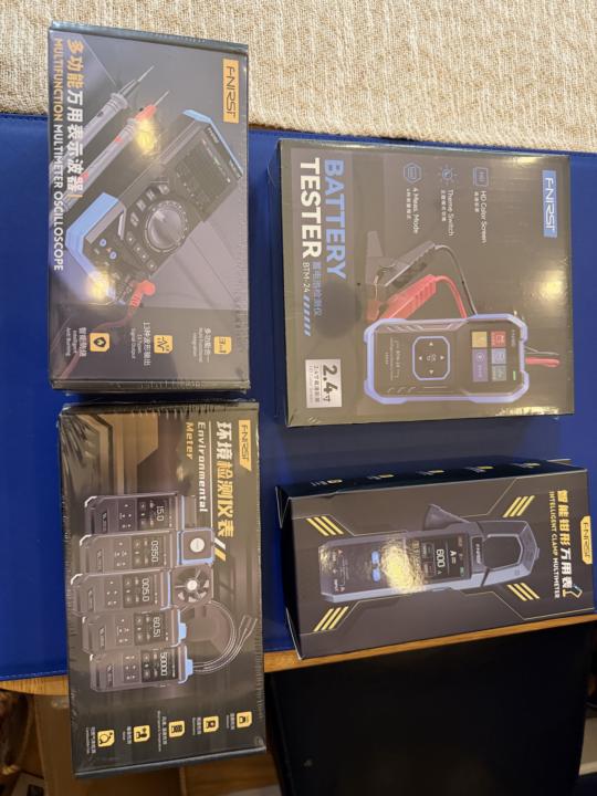
Fnisi
We have just got some new tools in to make some new videos,when we get another 10 paying members we will be giving away the amps clamp,get sharing your affiliate links on your socials 👌👌
0 likes • Mar 20
Is the amps clamp the same one from the training video for the short to ground on the transit? Never seen a short to ground tested that way before will definitely be trying it the next time I get one in the workshop 👍
0 likes • Mar 20
@Robert Shervill I’ve only got through a bit of the training so far but already learning new techniques. Definitely worth the subscription
1-4 of 4

@aaron-leneghan-6690
Hi my names is Aaron I run a small garage in Northern Ireland been out on my own now for just over 2 years
Active 5h ago
Joined Mar 19, 2026
Powered by